Cutting and processing of hard and brittle materials are the first set of procedures, thus this process plays a crucial role. In the past, cutting processes included internal (external) circular saw cutting, band saw cutting, etc., which exerted significant cutting deformation forces, resulting in severe damage to the material surface and subsurface after cutting, poor surface shape accuracy, and other reasons that made it difficult to meet the requirements of precision cutting of precious crystals.
Traditional cutting processes with low processing accuracy result in a significant amount of processing allowance for subsequent grinding and polishing processes, leading to a decrease in overall processing efficiency.
In 1974, Bowman J and H Mech adopted the method of reciprocating cutting using free abrasive to cut brittle materials. I Kao and his team have been dedicated to researching the principles and mechanical analysis of free abrasive machining (FAM) technology. They found that the processing time during semiconductor processing is directly proportional to the square of the processed crystal diameter.
The distribution of abrasive grains and the size of abrasive grain mixtures during free abrasive machining both have an impact on processing quality and material removal rate.
Past research has mainly focused on a single abrasive grain or grain size distribution, and the impact of the distribution of mixed-size abrasive grains on surface characteristics remains unknown. They utilized optical microscopes and image processing techniques to analyze surface features and types, establishing a model for the removal rate of mixed abrasive cutting. ABidiville et al. developed a fracture strength parameterized model based on wire tension, feed rate, and abrasive grain volume size. This model is only applicable to specific process conditions but provides guidance for sawing experiments.
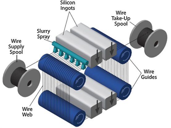
With the development of the photovoltaic industry, the multi-wire slurry sawing (MWSS) using free abrasive has gradually matured. It employs a longer wire with a diameter of 150 to 300 μm, cutting metal wire sizes ranging from 600 to 800 µm, and typically a wire tension of around 20N. Figure 1.18 illustrates the removal mechanism of multi-wire slurry sawing with free abrasive. Two reels are wound with long metal wires, with a tension roller on the right and a release roller on the left. The metal wires are wound in a corresponding manner, forming a parallel and closely spaced multi-wire processing mechanism guided by four wire guides.
During the cutting motion, the slurry injector sprays the slurry to specific locations. The moving wire saw carries the abrasive into the cutting zone, where the abrasives rotate in the cutting gap, generating forces that create cracks and fractures in the material. As the wire and abrasives move, they carry the debris out of the processing area, achieving the removal of brittle materials. The slurry is formulated by mixing polyethylene glycol (PEG) or common oil as the cutting fluid base, then adding abrasives (diamond or silicon carbide particles) and various additives. The cutting fluid possesses suitable viscosity, flow adaptability, and thermal conductivity, providing excellent suspension and dispersion stability for the abrasive micro-particles. The cutting fluid ensures the uniform movement of the abrasive particles by the wire saw.To sustain the cutting process, it is essential to reduce the generated cutting heat and chips effectively.

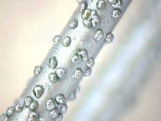
Free Abrasive Machining (FAM) can meet the purpose of narrow kerf cutting, but its surface form accuracy is difficult to control. When the wire saw cuts for a long time, it is challenging to introduce abrasives, reuse slurry circulation, leading to significant environmental pollution. During processing, the abrasives have a cutting effect on both the wire saw and the workpiece, resulting in a lower wire saw lifespan [34]. The Multi-Wire Fixed Diamond Abrasive Wire Saw (DWS) has a cutting efficiency 2-3 times higher than free abrasive cutting [36], and the recovery of cut material when cutting valuable crystals is receiving widespread attention. The fixed diamond wire saw employs a fixed method to attach diamond particles to the wire saw, generating significant cutting force and efficiency without relative motion between the diamond abrasives and the wire saw. The fixed wire saw commonly uses water-based coolant for processing, making the process easy to control with minimal pollution. Figure 1.19 depicts the Nickel-Based Electroplated Diamond Wire Saw.

The above figure shows the mechanism diagram of fixed abrasive multi-wire cutting, indicating that although the wire winding system or machine operation system has similar functions, there are significant differences in the material removal mechanisms between Free Abrasive Multi-Wire Sawing (MWSS) and Multi-Wire Fixed Diamond Abrasive Wire Saw (DWS). In the schematic below illustrating the free abrasive machining mechanism, the rapidly moving wire above carries suspended abrasives into the processing area. With the relative motion between the wire and the cutting material, the suspended abrasives rotate to cut the surfaces of the cutting material and the wire. The cutting material undergoes elastic deformation, plastic deformation, microcracks, and fracture, ultimately achieving material removal. Tribology refers to this process as three-body abrasion.


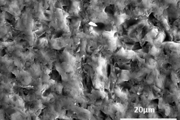
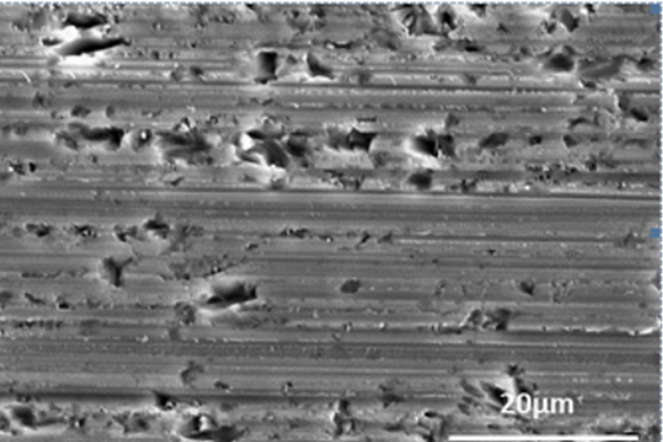
As mentioned above, in the past few years, the fixed diamond wire saw has rapidly developed, and many researchers are studying this new technology in terms of crystal slicing quality. From Figure chips after free abrasive cutting and chips after fixed diamond abrasive cutting, the surface morphology SEM images show the different surface morphologies produced by the two processing methods. Factors affecting the cutting quality of crystal materials include the total thickness variation (TTV) of the chips, surface quality (surface roughness, surface form accuracy), mechanical strength of the chips, and cutting losses. The material removal mechanisms of the two cutting methods, MWSS (three-body abrasion) and DWS (two-body abrasion), result in chips of different surface qualities.
If you have any question, please contact us